The Right Fit: How to Choose the Correct Thermal Pad Thickness for Your Application
Selecting a Thermal Interface Material (TIM) with the wrong thickness is a leading cause of thermal failure. Too thick, and it acts as an insulator. Too thin, and it leaves air gaps. The key is not the nominal gap, but the actual in-situ gap under mounting pressure, which is affected by component tolerances, board warp, and heatsink flatness. This guide provides a methodical approach.
Step 1: Measure the REAL Gap (The Most Critical Step)
- The Shim Method: Before final assembly, place soft, compressible shim stock (e.g., clay, plasticine) or solder wires of known diameter at multiple points across the interface.
- Assemble Prototype: Install the heatsink or cold plate with the shims in place, using the intended screws and torque.
- Disassemble and Measure: Carefully remove the heatsink and measure the compressed thickness of the shims. This is your Effective Assembly Gap (EAG).
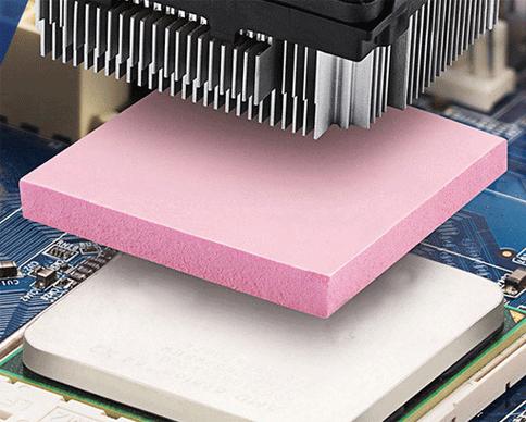
Step 2: Apply the 25-30% Compression Rule
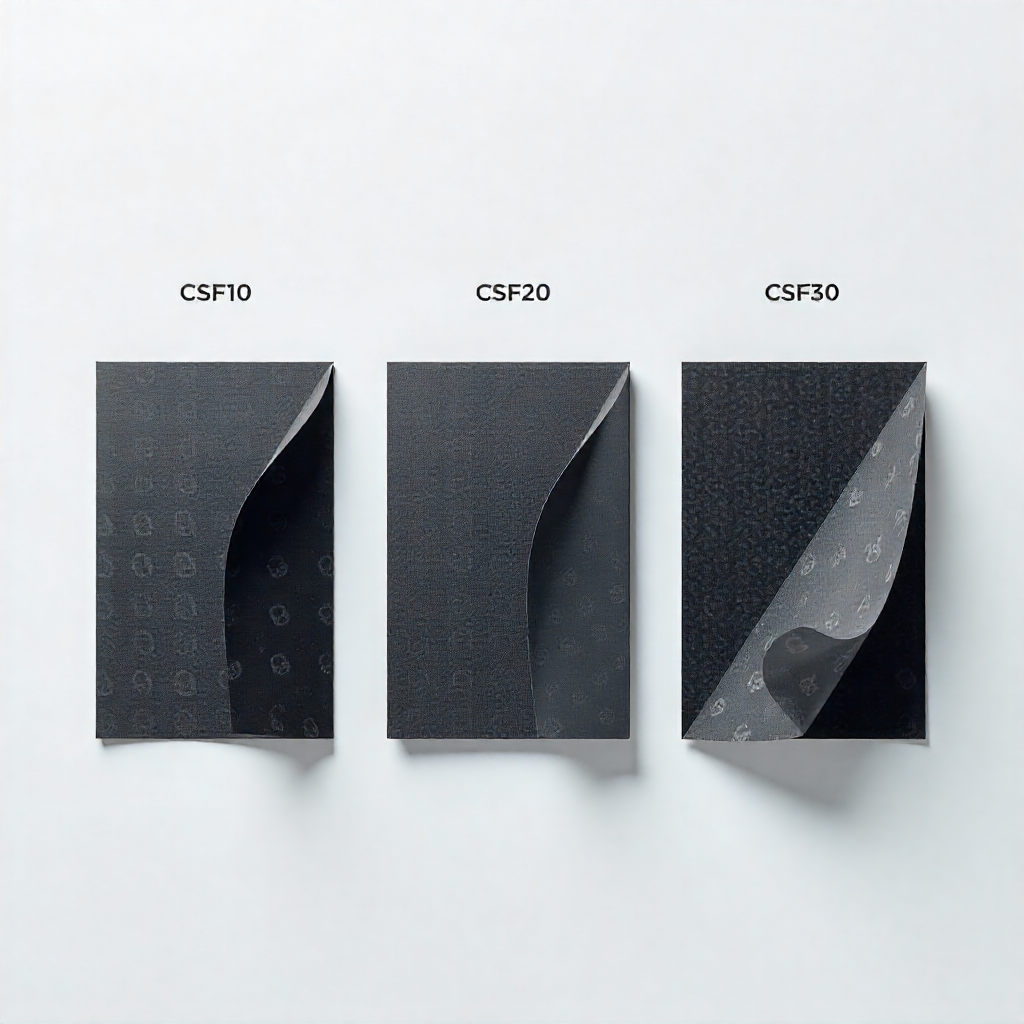
For optimal performance, a soft thermal pad should be compressed by 25-30% of its original thickness. This ensures enough pressure for good thermal contact without excessive stress that could damage components.
- Formula:Pad Thickness = EAG / (1 – Desired Compression %)
- Example: If your EAG is 0.5mm and you want 25% compression: Pad Thickness = 0.5mm / (1 – 0.25) = 0.67mm. You would select a 0.65mm or 0.70mm pad.
Step 3: Account for Material Behavior
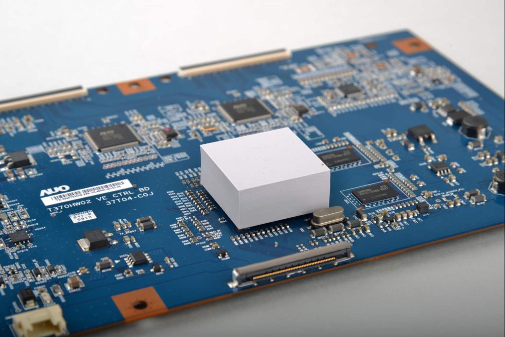
- Phase Change Pads/Greases: These flow to fill gaps. The target is to have them just slightly overfill the gap so pressure ensures full surface contact.
- Gap Filler Putties: These are designed for high compression (often 50%+) and irregular gaps. They are forgiving but can be messy.
- Harder, Graphite-Based Pads: Require high pressure and tolerate less compression. Use them only when the gap is very tight and controlled.
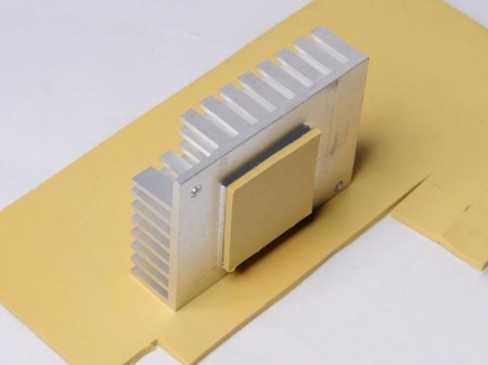
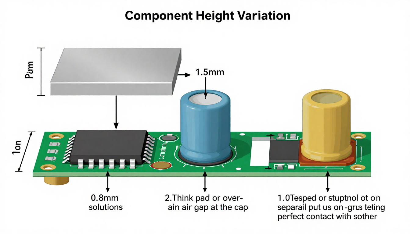
Advanced Tip for High-Variation Designs:
If you have components with vastly different heights (e.g., a tall capacitor next to a flat chip), consider a multi-thickness solution: a standard pad for the chip and a thicker, softer putty or a stepped pad design for the taller component.
Choosing thickness correctly is an engineering calculation, not a guess. It ensures the TIM works as designed, providing the lowest possible thermal resistance for your specific mechanical stack-up.