The GHz Frequency Squeeze: How TIM Dielectric Loss Tangents Drain Power in High-Speed Boards
As digital signal speeds breach 50+ Gbps and RF systems operate deep into millimeter-wave bands, every material in proximity to a conductor becomes part of the signal’s electromagnetic environment. While much attention is paid to the dielectric constant (Dk) of Thermal Interface Materials (TIMs), their dissipation factor (Df) or loss tangent (tan δ) at operational frequencies is a critical, yet frequently overlooked, source of signal degradation and power loss.
Understanding Dielectric Loss in TIMs:
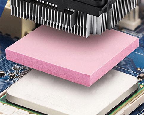
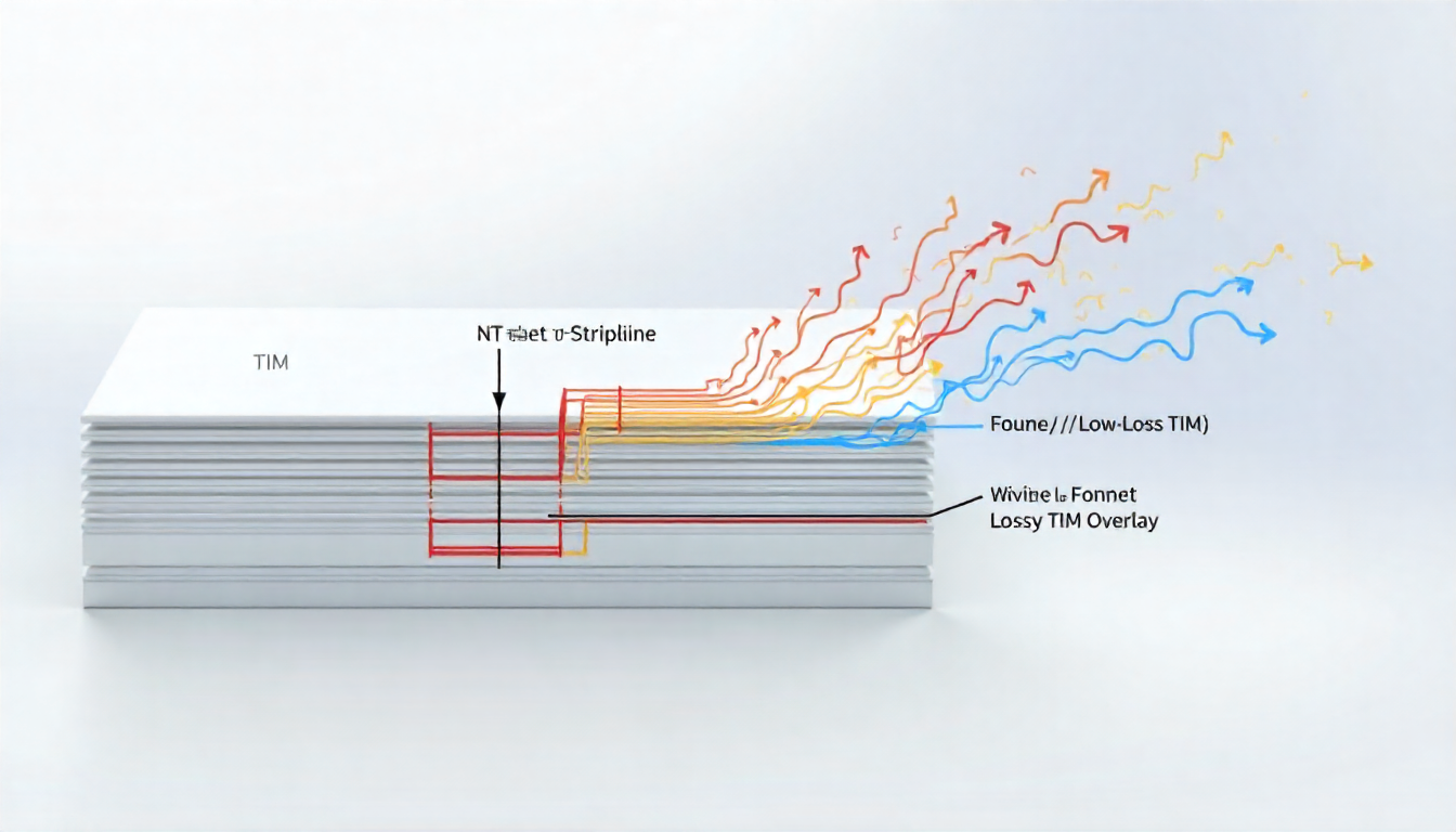
The loss tangent represents the material’s inherent inefficiency—the fraction of electromagnetic energy converted into heat within the dielectric itself. For a TIM near a high-speed trace or RF transmission line, a high Df means it acts as a parasitic power absorber, leading to:
- Increased Insertion Loss: The signal attenuates more over a given distance, reducing amplitude and closing the eye diagram.
- Reduced System Efficiency: In power-sensitive applications (e.g., 5G base stations, satellite transceivers), energy lost as heat in the TIM is wasted, increasing operational cost and thermal load—ironically, creating more heat to manage.
Material Drivers of High-Frequency Loss:
Loss is influenced by the polymer matrix and filler interface. Polar molecules or functional groups in the polymer can align with the high-frequency electric field, causing friction and heat. The interface between filler particles and the polymer can create microscopic charge polarization sites (Maxwell-Wagner-Sillars effect), significantly increasing loss at certain frequencies.
Designing for Low Loss:
- Demand Frequency-Specific Data: Supplier Df values measured at 1 MHz are irrelevant for GHz applications. Request data measured at your operational frequency (e.g., 2.4, 5.8, 28, 77 GHz).
- Model the Impact: Use 3D electromagnetic simulation software to model your specific stack-up with the TIM’s Dk and Df values included as material properties. Quantify the impact on insertion loss and impedance.
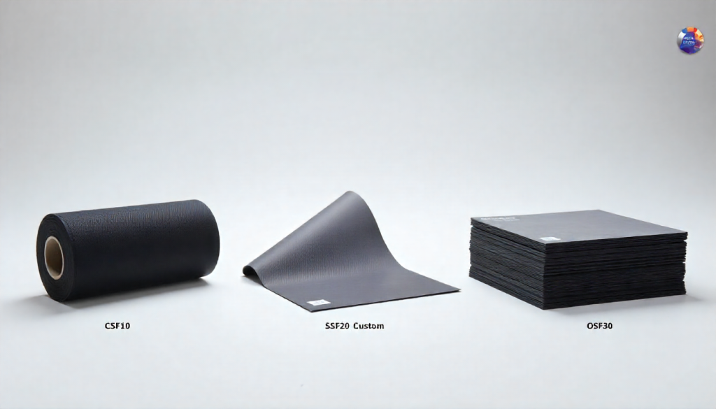
- Select Low-Loss Formulations: Certain polymer families (e.g., some polyolefins, engineered thermoplastics) and filler treatments are engineered for lower loss at high frequencies compared to standard silicone-based pads.
For systems where every decibel of loss counts, the TIM must be selected as carefully as the PCB substrate. We provide high-frequency dielectric property characterization for our materials, enabling you to make informed co-design choices that optimize both thermal and electrical performance.